BUILDING A QUADCOPTER
SO .... WHAT IS A QUADCOPTER ??
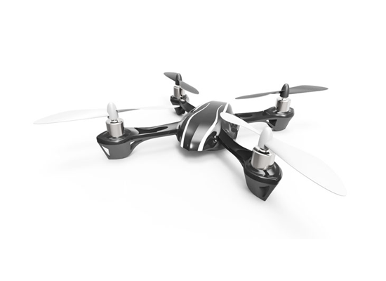
A QuadCopter is a helicopter with four rotors, so it’s also known as quadrotor. Because of its unique design comparing to traditional helicopters, it allows a more stable platform, making quadcopters ideal for tasks such as surveillance and aerial photography. And it is also getting very popular in UAV research in recent years.
The Quadcopters exist in many different sizes. From as small as a CD up to something as big as one meter in width.

On a regular helicopter has one big rotor to provide all the lifting power and a little tail rotor to offset the aerodynamic torque generated by the big rotor (without it, the helicopter would spin almost as fast as the propeller)
Unlike a helicopter, a quadrotor has four rotors all work together to produce upward thrust and each rotor lifts only 1/4 of the weight, so we can use less powerful and therefore cheaper motors. The quadcopter’s movement is controlled by varying the relative thrusts of each rotor.
These rotors are aligned in a square, two on opposite sides of the square rotate in clockwise direction and the other two rotate in the opposite direction. If all rotors turn in the same direction, the craft would spin would spin just like the regular helicopter without tail rotor. (if you are not sure what I mean, check out this video) Yaw is induced by unbalanced aerodynamic torques. The aerodynamic torque of the first rotors pair cancelled out with the torque created by the second pair which rotates in the opposite direction, so if all four rotors apply equal thrust the quadcopter will stay in the same direction.

To maintain balance the quadcopter must be continuously taking measurements from the sensors, and making adjustments to the speed of each rotor to keep the body level. Usually these adjustments are done autonomously by a sophisticated control system on the quadcopter in order to stay perfectly balanced. A quadcopter has four controllable degrees of freedom:Yaw, Roll, Pitch, and Altitude. Each degree of freedom can be controlled by adjusting the thrusts of each rotor.

DEGREES OF FREEDOM !
Yaw (turning left and right) is controlled by turning up the speed of the regular rotating motors and taking away power from the counter rotating; by taking away the same amount that you put in on the regular rotors produces no extra lift (it won’t go higher) but since the counter torque is now less, the quadrotor rotates as explained earlier.3.- control becomes a matter of which motor gets more power and which one gets less.
Roll (tilting left and right) is controlled by increasing speed on one motor and lowering on the opposite one.
Pitch (moving up and down, similar to nodding) is controlled the same way as roll, but using the second set of motors. This may be kinda confusing, but roll and pitch are determined from where the “front” of the thing is, and in a quadrotor they are basically interchangeable; but do take note that you have to decide which way is front and be consistent or your control may go out of control.


This illustrates how the adjustments made for each degree of freedom must work together to achieve a desired motion. Now, building and flying a quadrotor from a remote control is simple and fun and stuff, but people noting the inherently stable flight (in theory with equal speed of the motors the thing keeps itself level) and ease of control (only three functions and they are all basically take speed from one and put in the other), people love to make them autonomous (flies itself) and semi-autonomous.
COMPONENTS OF QUAD :
Frame
Frame is the structure that holds all the components together. The Frame should be rigid, and be able to minimize the vibrations coming from the motors.
A QuadCopter frame consists of two to three parts which don’t necessarily have to be of the same material:
- The center plate where the electronics are mounted
- Four arms mounted to the center plate
- Four motor brackets connecting the motors to the end of the arms
Most available materials for the frame are:
- Carbon Fiber
- Aluminium
- Wood, such as Plywood or MDF (Medium-density fibreboard)

Brushless Motors
A little background of Brushless motor. They are a bit similar to normal DC motors in the way that coils and magnets are used to drive the shaft. Though the brushless motors do not have a brush on the shaft which takes care of switching the power direction in the coils, and this is why they are called brushless. Instead the brushless motors have three coils on the inner (center) of the motor, which is fixed to the mounting.

Generally brushless motors spin in much higher speed and use less power at the same speed than DC motors. Also brushless motors don’t lose power in the brush-transition like the DC motors do, so it’s more energy efficient.
Brushless motors come in many different varieties, where the size and the current consumption differ. When selecting your brushless motor you should take care of the weight, the size, which kind of propeller you are going to use, so everything matches up with the current consumption. When looking for the brushless motors you should notice the specifications, especially the “Kv-rating“.
The Kv-rating indicates how many RPMs (Revolutions per minute) the motor will do if provided with x-number of volts. The RPMs can be calculated in this way: RPM=Kv*U An easy way to calculate rating of motor you need, check out the online calculator eCalc. It’s an amazing tool that helps you decide what components to purchase depending on the payload that you want to carry.
propellers
On each of the brushless motors there are mounted a propeller.
You might not have noticed this on the pictures, but the 4 propellers are actually not identical. You will see that the front and the back propellers are tilted to the right, while the left and right propellers are tilted to the left.
Like I mentioned before, 2 rotors rotates in the opposite directions to the other two to avoid body spinning. By making the propeller pairs spin in each direction, but also having opposite tilting, all of them will provide lifting thrust without spinning in the same direction. This makes it possible for the QuadCopter to stabilize the yaw rotation, which is the rotation around itself.


The propellers come in different diameters and pitches (tilting). You would have to decide which one to use according to your frame size, and when that decision is made you should chose your motors according to that. Some of the standard propeller sizes used for QuadCopters are:
- EPP1045 10 diameter and 4.5 pitch this is the most popular one, good for mid-sized quads
- APC 1047 10 diameter and 4.7 pitch much similar to the one above
- EPP0845 8 diameter and 4.5 pitch regularly used in smaller quads
- EPP1245 12 diameter and 4.5 pitch used for larger quads which requires lot of thrust
- EPP0938 9 diameter and 3.8 pitch used in smaller quads.
But in general when selecting propellers you can always follow these rules:
- The larger diameter and pitch the more thrust the propeller can generate. It also requires more power to drive it, but it will be able to lift more weight.
- When using high RPM (Revolutions per minute) motors you should go for the smaller or mid-sized propellers. When using low RPM motors you should go for the larger propellers as you can run into troubles with the small ones not being able to lift the quad at low speed.
ESC – Electronic Speed Controller
The brushless motors are multi-phased, normally 3 phases, so direct supply of DC power will not turn the motors on. Thats where the Electronic Speed Controllers (ESC) comes into play. The ESC generating three high frequency signals with different but controllable phases continually to keep the motor turning. The ESC is also able to source a lot of current as the motors can draw a lot of power.

The ESC is an inexpensive motor controller board that has a battery input and a three phase output for the motor. Each ESC is controlled independently by a PPM signal (similar to PWM). The frequency of the signals also vary a lot, but for a Quadcopter it is recommended the controller should support high enough frequency signal, so the motor speeds can be adjusted quick enough for optimal stability (i.e. at least 200 Hz or even better 300 Hz PPM signal). ESC can also be controlled through I2C but these controllers are much more expensive.
When selecting a suitable ESC, the most important factor is the source current. You should always choose an ESC with at least 10 A or more in sourcing current as what your motor will require. Second most important factor is the programming facilities, which means in some ESC you are allowed to use different signals frequency range other than only between 1 ms to 2 ms range, but you could change it to whatever you need. This is especially useful for custom controller board.
Battery
As for the power source of the quadcopter, I would recommend LiPo Battery because firstly it is light, and secondly its current ratings meet our requirement. NiMH is also possible. They are cheaper, but it’s also a lot heavier than LiPo Battery.

Battery Voltage
LiPo battery can be found in a single cell (3.7V) to in a pack of over 10 cells connected in series (37V). A popular choice of battery for a QuadCopter is the 3SP1 batteries which means three cells connected in series as one parallel, which should give us 11.1V.
Battery Capacity
As for the battery capacity, you need to do some calculations on:
- How much power your motors will draw?
- Decide how long flight time you want?
- How much influence the battery weight should have on the total weight?
A good rule of thumb is that you with four EPP1045 propellers and four Kv=1000 rated motor will get the number of minutes of full throttle flight time as the same number of amp-hours in your battery capacity. This means that if you have a 4000mAh battery, you will get around 4 minutes of full throttle flight time though with a 1KG total weight you will get around 16 minutes of hover.
UIMU – Inertial Measurement unit
The Inertial Measurement Unit (IMU) is an electronic sensor device that measures the velocity, orientation and gravitational forces of the quadcopter. These measurements allow the controlling electronics to calculate the changes in the motor speeds.
The IMU is a combination of the 3-axis accelerometer and 3-axis gyroscope, together they represent a 6DOF IMU. Sometimes there is also an additional 3-axis magnetometer for better Yaw stability .
 |
| IMU Sensor from sparkfun electronics |
Magnetometer
The accelerometer cannot sense yaw rotation like it can with roll and pitch, and therefore a magnetometer is sometimes used.
A magnetometer measures the directions and strength of the magnetic field. This magnetic sensor can be used to determine which way is south and north. The pole locations are then used as a reference together with the Yaw angular velocity around from the gyroscope, to calculate a stable Yaw angle.

Flight Controller :
Here is a comprehensive list of ready to go flight controller boards:
You can either make your own controller board by making use of Adruino board orlese make use of ready to fly controller board .
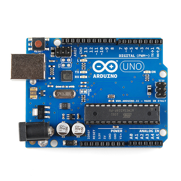 |
| ADRUINO board from Sparkfun electronics |
 |
| ARDUPILOT ATMEGA |
 |
| Hard ware layout of Ardupilot |
RC Transmitter
QuadCopters can be programmed and controlled in many different ways but the most common ones are by RC transmitter in either Rate (acrobatic) or Stable mode. The difference is the way the controller board interprets the orientations feedback together with your RC transmitter joysticks.


GPS , ULTRASONIC SENSOR , BAROMETER :
In Rate mode only the Gyroscope values are used to control the quadcopter. The joysticks on your RC transmitter are then used to control and set the desired rotation speed of the 3 axes, though if you release the joysticks it does not automatically re-balance. This is useful when doing acrobatics with your quadcopter as you can tilt it a bit to the right, release your joysticks, and then your quadcopter will keep that set position.
A GPS module talks to the satellite and retrieve accurate location information. We can use this information to calculate speed and path. It is especially useful for autonomous quadcopters which needs to know its exact position and which way to fly.
An ultrasonic sensor measures the distance to the ground, i.e. altitude. This is useful if you want to keep your quadcopter a certain distance from the ground without having to adjust the height it’s flying at constantly yourself. Most of these sensors has a range between 20cm to 7m.
When you gets higher, you might want to use a barometer. This sensor measures humidity and pressure to work out the altitude, so when the quadcopter is close to the ground (where these two factors doesn’t change much), it becomes ineffective. Therefore it is also common to use both of them at the same time.
 |
| GPS module from sparkfun electronics |
| ULTRASONIC SENSOR |
CONCLUSION

Thus an overview about selecting a controller board and building up your own quadcopters has been described shortly and precisely.
hope , you are now ready to build your own multirotors in your home.
GOOD LUCK !!!
Do check in regularly to see what we are doing in our project in overcoming days .................. :)
No comments:
Post a Comment